
The Roland LEF2-200 and LEF2-300 UV printers are quite remarkable machines. Quick, reliable, and with consistently top quality results - we're really happy and lucky to be able to run two of them to make many of our products!
One little issue we had with them was aligning things in the printer with high precision. With many of our earrings, we often need to accurately line up the printing within 0.05mm, to get them to look correct when printed. (Well, and that I'm a perfectionist too). The printer itself being a general purpose machine doesn't come with a jig that's suitable for our use case. There are some commercially available jigs for these printers, but most of them are focused on printing batches of specific products like phone cases or pens. We needed something a little more general.
We've talked about the level of precision that we use in a previous blog post about UV printing. To properly achieve this, we've made our own custom jigs, that have gone through several revisions to be the form that they are today.
I'm pretty confident that the current revision is the final revision - after several months of use we've had a very trouble free run of earrings due to these jigs!
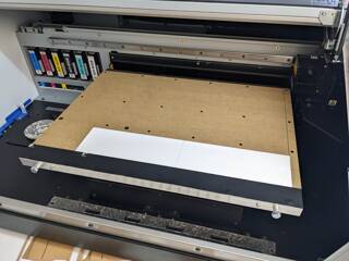
The printers ship with a flat table... and not much else! This is by design; the printers are used in a wide variety of ways and as such you'll need a jig or setup that works best with your products. The flat table is well documented by the manual, and includes a series of M4 threaded holes for you to add your own jigs to.
The LEF2-200 comes with a line engraved into the aluminium table which is the printable area. In theory, you can line up items with this line to get them in the spot that you'd like. The LEF2-300 has a vacuum table, and because of this, doesn't have the engraved line. Instead, it has a small square hole right at the origin to show you where it is.
The printers ship with some basic straight plastic bars and countersunk screws. The idea is that you screw them onto the sides and push your work up against them to get them into the origin. While helpful, these were not accurate enough for our purposes. They are 3mm tall, which means we can't properly print on 2mm thick acrylic (something we do all the time), and they flexed as they didn't have a screw right at the origin, meaning that your workpiece could move. Finally, when installed, they're about 0.3-0.4mm outside the printable area; that is if you push something up against it, the printer can't reach the first 0.3-0.4mm of the workpiece.
But that's ok - you're meant to make jigs that fit your work and work style!
After working with the printers for a while and working out our processes, we worked out what we need from a jig:
To be honest - after running laser cutters for several years - working out how to properly align things with UV printers was quite a different ballgame! With the lasers, when we do laser engraving, we normally engrave first, and then cut out the panel afterwards, meaning that the laser has everything in the correct location - it "self jigs" itself. For engraving on existing items like chopping boards, we cut temporary jigs out of cardboard and then insert the board, and as it's cut each time, it's always in the right spot and square to the laser, as the laser just made it.
But the printers are a different ballgame - they can't cut their own jigs for positioning, so you've got to use the facilities that the printer provides to align everything. This was the steepest learning curve for us - but once we mastered it, we can very quickly and accurately print many items.
Our first jig revision was a very simple L piece cut in acrylic. We cut it from 2mm thick acrylic, and it matched the origin exactly. To affix it to the printer, we used 4mm grub screws and self-threaded the acrylic, so as to have the surface flush and not run into the print heads.
This met some of our requirements. It allowed us to print on items 2mm or thicker. It gave us a nice origin to push up against. But even though it was precisely laser cut and screwed to the bed, it was not square to the print head which caused some challenge lining up earrings.
We also discovered that even though it was up against the official origin, the printer couldn't reach the first 0.5mm of the print area. This was a relatively easy fix; we made the jig cover 1mm of the print area, and then adjusted the printers origin (which allows adjustment of the feed and scan in 0.1mm increments) to change start point. This allowed us to accurately position the start point.
This one also shuffled around each day, giving ever so slightly different results. The actual reason for this wasn't understood for a while, but now that we know why, it would have saved a lot of hair pulling!
Revision 1 went through several variants before we moved onto revision 2.
The next revision was a different approach. This time, we made a panel that covered the whole printer. It was made from two layers of acrylic. The bottom layer was 3mm acrylic and covered the entire bed. The top layer was made in two parts; a L shape 3mm acrylic piece that went along the right and bottom side, and formed the origin perimeter, and a rectangular 2mm acrylic piece that covered the rest. To hold it down, the 3mm bottom layer had 4mm holes (for the M4 bolts) and the 2mm layer had larger holes (10mm) so you could put some thin head hex bolts through it and end up with a flush surface (think countersunk, but without angled sides).
With this revision, we deliberately made it 2mm bigger on the front and right sides; and adjusted the printers origin in until the origin matched our origin. This means that we lost 2mm of printable width and 2mm of printable depth; but this didn't affect any of our print jobs.
To get the ability to square the jig, the bolt at the origin was fixed, but one of the bolts on the left hand side had a slot, so you could rotate the jig around the origin, so you could shuffle it and then fix it in place, doing a test print each time until it was perfectly square to the printer.
We got quite a bit of life out of these jigs. They worked well and gave us reasonably consistent results. But there was one area that let them down - squareness. It was very time consuming to get them square, as every small move had a large change to the squareness of the jig. Even doing up the bolts could shift the squareness slightly.
The consistency wasn't great either. One day we'd be able to print squarely, and then we'd come back the next day, and the origin was perfect, but it wasn't square any more. It was then that we made a discovery which is likely obvious to anyone who manufactures equipment like this...
Yep, that's right. Fairly basic physics, and very well documented, and lots of the infrastructure in our life has examples of this - like the expansion gaps in concrete paths; expansion gaps in bridges; expansion gaps in railway lines. In our specific case, the acrylic that the jig was made of expands at different rates to the aluminum that the table is made from. We had bolted this acrylic tightly down to the aluminum table. The bolts didn't move, but as the acrylic expanded and contracted faster, it warped and was giving us 0.1-0.2mm squareness errors across the table - more than enough to mess up our work and cause issues!
The short term fix with the revision 2 jigs was to change the square fixing bolt - and just that one - and put a rubber o-ring betwen the bolt head and the acrylic table. This rubber o-ring was able to shift slightly as the acrylic expanded and contracted, taking off the stress and preventing the acrylic from warping. This worked quite well for a while, until we were able to replace the jig with revision 3.
Technically, this is revision 3.5; there was a revision 3.0 before it which was quite similar and proved that the concept would work. However, revision 3.0 was only made to cover the first 100mm of the bed, and more than proved the concept, but revision 3.5 covered the whole bed.
Given we have CO2 laser cutters, we solve most of our problems with acrylic or wood. Personally, I don't have a lot of metal working experience, and our CNC machines are not suitable for metal work, so I tend to look for other solutions first. But this one needed aluminum to match the bed, so it would expand and contract at the same rates.
The first step was to visit the local hardware store (well, hardware store chain...) and find what aluminium profiles they had on hand. The next step was to take this information and draw it up on a computer to work out where all the parts go, and where the holes would go, and how it would fit together. I modelled this in Fusion 360, as this is the tool we have a subscription for, and it's covering off a lot of different products and use cases for us.

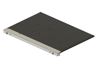

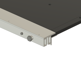
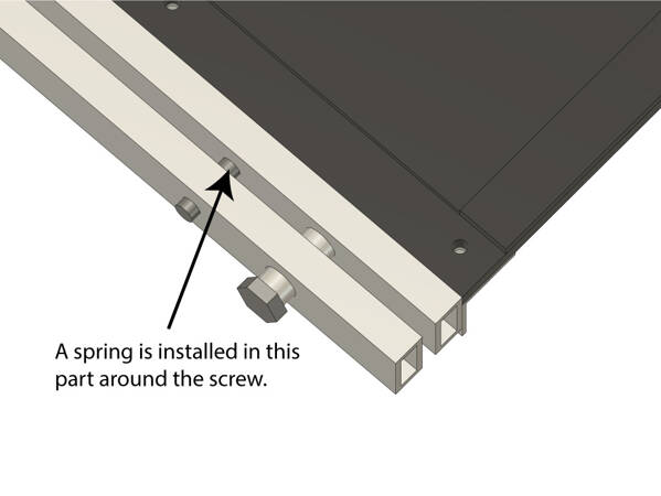

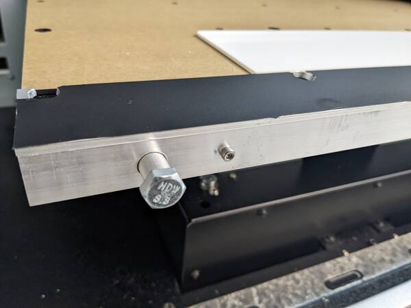
Alright, let's walk through this one and explain how it works. You can see in the closeup that there is two rectangular tubes mounted with a 5mm gap in between them. Behind them in an angle profile that connects the back one to the printer table. The front one is then attached to the 40mm wide flat aluminium bar that's on the top. You'll see that there is a bolt and then a small screw next to it. The bolt is fixed - it's a M8 bolt, but around the bolt is a 10mm aluminum tube. The right hand side is identical. The 10mm tube is kind of a linear rail, that allows the front rectangular tube to move forward and backward relative to the back one, taking the flat bar with it. The flat bar forms the front of the origin area and given that it's nicely machined aluminum, it's dead straight. The the smaller screw is the adjustment screw for square - between the front and the rear bar it has a spring contained by the small screw. The idea is that you do up the small screw to compress the spring, and undo it to release the spring. The front bar then can move forward and backward slightly. But you can actually move the left and right hand side forward or backward separately, effectively rotating the flat bar, allowing you to square up the flat top bar exactly to the printer by doing a series of test prints.
It's designed also so the flat bar takes up the first 0.5-1mm of the print area as well; the intention is to set it up and then adjust the printer origin in until it matches up.
The flat bar at the top lines up with the top of the printer table exactly. Without anything else, this means you could only print on objects 3mm or thicker. But then we top the table with a 2mm thick piece of acrylic; both to protect the table and to raise your workpiece up 2mm, meaning that lip on the flat bar is now 1mm - meaning you can print on objects from 1mm thick. On the right hand side, we have a 3mm piece of acrylic that acts as the right hand origin piece, which also gives us a 1mm lip. The right hand bar is also 1mm bigger than it needs to be, to allow adjusting the origin correctly.
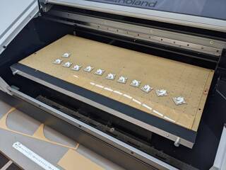
For the LEF2-300 jig, we also cut vacuum holes in the 2mm acrylic panel, to allow the vacuum to flow up through those holes. For our use case, we generally only need vacuum on the first 100mm of the table, and on the right hand 100mm of the table, so we deliberately only cut those holes. The 2mm panel then blocks all other vacuum holes, increasing the vacuum to the unblocked holes as a bonus.
This then meets all of our requirements.
As I mentioned before, metal working isn't one of my strong points. More like not one of my points! And we don't really have CNC machines suitable for working with metal, so this one had to be machined and assembled by hand.
In our factory unit complex, we work with other businesses who do have metal working experience, so we kindly got them to cut down the aluminium extrusions to the correct length with their proper cutting equipment. They were all cut to be the exact width of the printer bed.
The rest of it was drilling holes! For this one, I exported some flat views of the various components in Fusion 360, which I then laser cut from 2mm acrylic. Before I cut the acrylic, I put some of our sign grade double sided tape on the back. While not a permanent adhesion to aluminium, it was more than suitable for sticking down the acrylic onto the aluminium as a drilling template. To make sure various parts matched up later, the profiles that needed matching holes were clamped together, and then using a drill press to get the holes square, I drilled through both of the profiles at the same time. There were three clamped combinations that were required:
Now! Here is the little trap. To make it easier to assemble, I decided to tap some of the holes to add threads to them, rather than using nutserts or similar. From an engineering point of view, this is a bit weaker as most of the threads were in 1mm or 2mm thick aluminum, and there wasn't a margin for error if the thread was damaged. So I just went carefully. This did mean double drilling some holes, though. For example, when the front mover bar and the back fixed bar were drilled together, I drilled a 2.5mm hole to allow it to be tapped and threaded. But then I had to redrill the front mover bar holes again at 3mm to allow the screw to pass through freely. The same thing happened with the 7.5mm holes (tapped to fit M8) and the 10.5mm holes on the front to allow the aluminium round tube through. On the back of the bracket, this also happened.
The bracket that fixes the bar to the table had to be quite precise to allow the flat bar to end up exactly on the surface of the table, and enough so you can gently move it in and out to adjust it. When I first made it, it was ever so slightly too close - like 0.3mm too close together. This was actually an easy fix - I made the bracket side holes 4mm, giving the M3 screws a little bit of wiggle room. I then placed it on the table, pushed it up and tightened up the screws.
To fix the flat bar on the top to the front mover bar, I used small M3 countersunk screws that I had on hand. This required countersinking the holes, but I had tools on hand to do this.
The final quirk on the top panel is to add holes to allow the head refresher to sit correctly on the table. In hindsight, I could have actually reprogrammed the printer to move where the head refresher sits, but I do try to keep the machines in their stock configuration where possible to prevent any issues or confusion in the future. To get this one to work, I drilled holes in the bar in the appropriate locations. However, they had to be a bit oversized to allow for the flat bar to be adjusted, and they were close to the edge. The net result was that they kind of spilled over the edge of the flat bar! It looked a bit rough, but a little bit of adjustment with an angle grinder and some work with a file cleaned it up.
The last part - a quite important part - was to make the top flat bar less reflective, as the UV light from the printer lamps can reflect back and damage the print heads! To fix this one, I used some spare matte black vinyl that I had on hand, carefully installing it on the top and trimming it so that it didn't interfere with the main alignment edge that items get pushed up against.
Then, the table covers were laser cut and installed. For the LEF2-200 jig, we used small quantities of double sided tape under the main table cover to keep it in place. The double sided tape allows it to flex and move slightly as the aluminium table and the acrylic change size in temperature. However, this still warped a touch, although it didn't put any of the printer components at risk, nor did it prevent any work from being completed. For the LEF2-300, we used a different approach, as I didn't want to get double sided tape over the vacuum holes! For this one, we cut the main screw holes smaller - at 3.5mm - and self-threaded them with some M4 grub screws, such that it ended up with a flush surface. The screws don't have a lot of grab as you're only threading that top 2mm in the acrylic - but it's more than enough to get it to stay in place. At the front where we couldn't access the holes as the main jig covered them, we used a small quantity of double sided tape manually placed between the vacuum holes to keep it in place, which has worked really well.
The installation was a resounding success, and the accuracy of the prints and setups since installation has been phenomenal. I was able to successfully square the print bed in just three test prints - compared to 10 or more for past revisions. After 24 hours, the acrylic and aluminum all settled into place and now I have very repeatable print setups.


I've shared the Fusion 360 designs online which you can view in 3D, or download as part of making your own ones.
If you have any questions, please contact us!
"Absolutely stunning. Bought for my mother-in-law for her birthday and we love it so much that we are getting ourselves one. She has received so many compliments about it!"